If there were no change in its velocity -- if it were to somehow instantaneously change direction with no deceleration and acceleration -- the graph of its displacement would look triangular.
This sort of triangular function can be useful for representing constant periodic linear change -- back and forth, up and down, etc. -- between two extremes. In terms of sound, it's important to remember than the impression of linear change in the subjective phenomena of pitch and loudness actually correspond to exponential or logarithmic change in the empirical measures of frequency and amplitude.
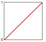
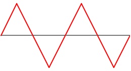
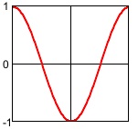
It's important to understand that a triangle function in pitch or decibels is not the same as a triangle function in frequency or linear amplitude. For example, a triangular displacement up and down from a central pitch by a tritone (+ or - 6 semitones) is exponential in frequency, and is a greater change upward in Hertz than it is downward. That is, a shift of 1/2 octave is a greater number of Hertz at higher frequencies than at lower frequencies, and a linear pitch change corresponds to an exponential curve in frequency, as illustrated in the following two visualizations. The first image depicts a linear change in pitch, as occurs in the program.
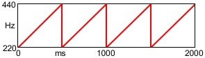
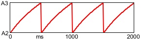
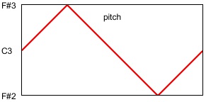 The second image depicts the change in frequency that corresponds to that triangle function in pitch.
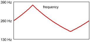 Note that the change in frequency is exponential rather than linear, and that a greater change of frequency is needed to go up a given pitch interval than is needed to go down the same pitch interval. In this case, to go from middle C (261.6 Hz) up to F# (370.0 Hz) is a difference of 108.4 Hz, while going down to F# (185.0 Hz) is a difference of 76.6 Hz. In Max the mtof or mtof~ object takes care of this translation from pitch to frequency for you. The formula in use is ƒ = 440.(2^(69.-p)), where p is the pitch in MIDI terminology (MIDI 69 = A 440 Hz).
A similar translation from linear to exponential is needed to go from the level in decibels, which is a logarithmic descriptor, to amplitude, which is on a linear scale. The formula used by the dbtoa and dbtoa~ objects to perform this translation is a = 10.^(d/20.), where d is the level in decibels relative to the maximum possible value, 1.
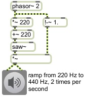
This program demonstrates the use of a triangular function to make periodic changes of pitch and loudness.
The second image depicts the change in frequency that corresponds to that triangle function in pitch.Note that the change in frequency is exponential rather than linear, and that a greater change of frequency is needed to go up a given pitch interval than is needed to go down the same pitch interval. In this case, to go from middle C (261.6 Hz) up to F# (370.0 Hz) is a difference of 108.4 Hz, while going down to F# (185.0 Hz) is a difference of 76.6 Hz. In Max the mtof or mtof~ object takes care of this translation from pitch to frequency for you. The formula in use is ƒ = 440.(2^(69.-p)), where p is the pitch in MIDI terminology (MIDI 69 = A 440 Hz).A similar translation from linear to exponential is needed to go from the level in decibels, which is a logarithmic descriptor, to amplitude, which is on a linear scale. The formula used by the dbtoa and dbtoa~ objects to perform this translation is a = 10.^(d/20.), where d is the level in decibels relative to the maximum possible value, 1.
This program demonstrates the use of a triangular function to make periodic changes of pitch and loudness.
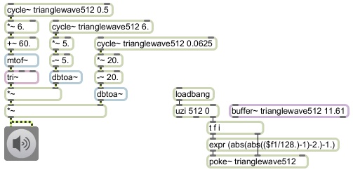
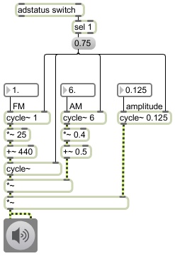
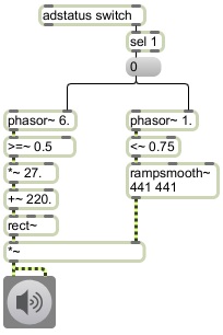
Instead of the cycle~ objects in this program reading from the default wavetable of 512 values in the form of a cosine function, we have to make a triangular function in a wavetable and read from that. The lower-right portion of the program creates and stores that function. When the program first starts up, it uses a mathematical expression to place 512 values in the form of a triangle wave into memory in a buffer~ object. (The size of the buffer -- 11.61 -- is expressed in milliseconds; at a sampling rate of 44,100 Hz, 11.61 milliseconds is 512 samples.)
The carrier oscillator is a tri~ object. Similarly to the saw~ and rect~ objects, tri~ generates a signal with a spectrum like that of a triangle wave, but one that limits its upper partials to avoid aliasing. This carrier oscillator's frequency and amplitude are controlled by three low-frequency oscillators -- the cycle~ objects reading from the triangle function in the buffer~. The triangle functions of the control oscillators are expressing values in terms of equal-tempered semitones and decibels, which correspond to our perception of pitch and volume, and those values are then converted to frequency and amplitude by the mtof~ and dbtoa~ objects.
Lets look at each of the uses of the triangle function here. At the top we have a triangle control oscillator with a frequency of 0.5 Hz, which means that it completes a cycle once every 2 seconds. Its amplitude is scaled by 6 and offset by 60, so it oscillates around the central value of 60, up as high as 66 and down as low as 54. This function is used to define the pitch, which is then translated into frequency by the mtof~ object and used to control the frequency of the carrier oscillator, the tri~ object. As in the other examples of classic control functions such as pulse wave, sawtooth wave, and sine wave, we use the triangle wave here as the carrier oscillator so that you can hear its timbral character. A triangle wave contains energy only at odd harmonics of the fundamental, with the amplitude of each partial proportional to the square of the inverse of the harmonic number. Thus, its timbre is richer than a sine tone, but mellower than a sawtooth wave.
The second triangle control oscillator has a frequency of 6 Hz, and serves to create an amplitude tremolo for the carrier oscillator. The control oscillates around -5 dB, going as high as 0 dB and as low as -10 dB. This level control is translated into amplitude by the dbtoa~ object and is used to control the amplitude of the carrier wave, creating a 10 dB fluctuation of amplitude 6 times per second.
The third triangle control oscillator has a frequency of 0.0625 Hz (1/16 Hz), so it completes a cycle only once every 16 seconds. This exerts a more formal function, creating a swell of the overall amplitude every 16 seconds, like a master volume knob, ranging as high as 0 dB and as low as -40 dB.
So in this one program we see the triangle function used 1) as a carrier waveform, for its timbral effect, with a frequency ranging from 185 to 370 Hz, 2) as a control function to create expressive amplitude tremolo at a rate of 6 Hz, 3) as a control function to create pitch glissando at a rate of 1/2 Hz, and 4) as a control function to create crescendo/decrescendo at a rate of 1/16 Hz.
Admittedly, the sound of an octave-wide pitch glissando is not terribly attractive; it's more like a siren than a musical gesture. But this program demonstrates several uses of this particular control function (timbre, glissando, tremolo, and dynamics), and shows the aesthetic effect of its characteristic shape.


.jpg)