Max doesn't really provide a pulse wave generating object, but it's easy enough to create an ideal pulse wave by combining a phasor~ object, which ramps periodically from 0 to 1, and a <~ object, which will output only 1 or 0 depending on whether its input is less than a given value. For example, if you use <~ to test whether the value of the phasor~ is less than 0.5, the output will be 1 for the first half of the phasor~'s ramp, and 0 for the second half, resulting in a square wave.
We can then scale and offset the output of >~ to obtain a periodic alternation between any two desired values. In terms of musical pitch, a periodic alternation between two values is known as a trill or, in the case of a wider interval, a tremolo, and is usually at a fast but still sub-audio rate from about 8 to 18 notes per second. When the alternation takes place at an audio rate, the wave is heard as a pitched tone containing only odd harmonics, with the amplitude of each harmonic inversely proportional to the harmonic number. Thus, if the waveform has amplitude A, the fundamental (first harmonic) has amplitude A, the third harmonic has amplitude A/3, the fifth harmonic has amplitude A/5, etc. This means that upper harmonics may exceed the Nyquist frequency, possibly causing unwanted audible aliased frequencies. So for times when a rectangle waveform is desired for a carrier oscillator, there is an object called rect~ that generates a wave with a spectrum very similar to a rectangle wave, but that only produces audible harmonics up to the Nyquist frequency.
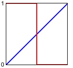
When a rectangle wave spends the same amount of time on 1 as it spends on 0, as in the above example, the wave is called a square wave. The amount of time the wave spends on 1, expressed as a fraction of one entire cycle, is called the duty cycle; in the case of a square wave the duty cycle is 0.5 because the wave spends 1/2 of its time at the value 1. However, a rectangle wave can have a duty cycle ranging anywhere from 0 to 1, which will allow a variety of alternation effects when the wave is used as a control function, and which will have a timbral effect when the wave is used as a carrier tone. For example, if we use 0.75 as the comparison value in the <~ object, the object's output will be 1 for 3/4 of each cycle of the phasor~, giving a rectangle wave with a duty cycle of 0.75.

This program demonstrates the use of a pulse wave as a control function and as a carrier waveform, using modulator pulse wave LFOs to control both the frequency and the amplitude of the carrier wave.
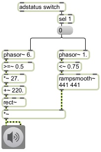
In this example a square wave at a rate of 6 Hz is used to modulate the frequency of the carrier oscillator back and forth between 220 Hz and 247 Hz, which gives the impression of a musical trill between A 220 and the B above that, at the rate of 12 notes per second. In this case, rather than use a <~, we use a >=~ object so that the square wave will start with a 0 value, thus starting the trill on A 220. Note that for the carrier oscillator, the one we actually listen to, we have used the rect~ object, which gives a band-limited pulse tone that resists the aliasing effects of an ideal rectangle wave.
To control the amplitude in this example we use a rectangle wave with a rate of 1 Hz and a duty cycle of 0.75. The effect is that we hear the sound for 3/4 of a second, followed by 1/4 of a second of silence; we hear 9 notes of trill followed by three notes' worth of silence.

Because an instantaneous switch from an amplitude of 0 to an amplitude of 1 or vice versa would cause a click, we use the rampsmooth~ object to interpolate linearly to the new amplitude value over 441 samples (10 milliseconds).
No comments:
Post a Comment